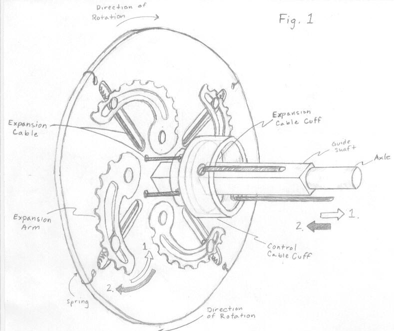
This week, I was able to address a persistent constrain of expanding chain ring systems like VECTr – namely, ensuring the design will fit the pitch of a bike chain. Standard chains have a half inch pitch, which means each roller of the chain is half an inch from its neighbor. Thus the teeth on chainrings are half an inch from their neighbors as well, so they can fit with each roller of the chain. The first constraint I encountered was that the system would not be able to spread the teeth out as the gear radius expanded. My initial solution was to use gear segments (initially conceived as spiraling out from one hinged end – see my previous post). But the space between gear segments still has to accommodate the pitch of the chain. Each gear segment must be a whole integer number of links from the next gear segment (1, 2, 3, etc.; not 1½ , 2.33 or some fraction of a chain link) so that when the next segment engages the chain, there will be a tooth ready to fit over a roller on the chain, and subsequent teeth can fit into the pitch of the chain smoothly.
As I have been refining the VECTr design to move towards an actual prototype, I still have to design the notches in the radial arms of the base plate at the precise position where the teeth of the gear segments will match the chain pitch. That means they have to be a whole integer number of chain rollers from the next gear segment. So, when VECTr has the size of a 50 tooth chainring, the adjacent gear segments are six chain rollers apart from each other, or 3 inches (since the pitch of a bicycle chain is ½ inch). When VECTr has the size of 45 tooth chainring, the gear segments must be five rollers apart or 2½ inches apart, and so on. The measurements must be whole integer multiples of ½ inch (not fractional increments like 2.75 or 1.33 inches apart) if the chain is to run smoothly over the device, and not skip or slip. (Slipping was a problem with working model, since tooth pitch was off.) Getting the right distance between gear segments has turned out to be harder that I originally thought!
To solve this problem, I had to reach back into my memory and dust off my limited knowledge of high school trigonometry. Thanks to the beauty, symmetry and order of geometry in general, right triangles in particular, and that old mnemonic SOH CAH TOA (sine=opposite/hypotenuse, cosine=adjacent/hypotenuse, and tangent=opposite/adjacent) I was able to identify the proper locking positions of the gear segments on radial arms as 72 degree angles from each other (since there are five in the 360 degree circle). The illustration below shows the calculations I made after some struggles to remember basic algebra and trig.
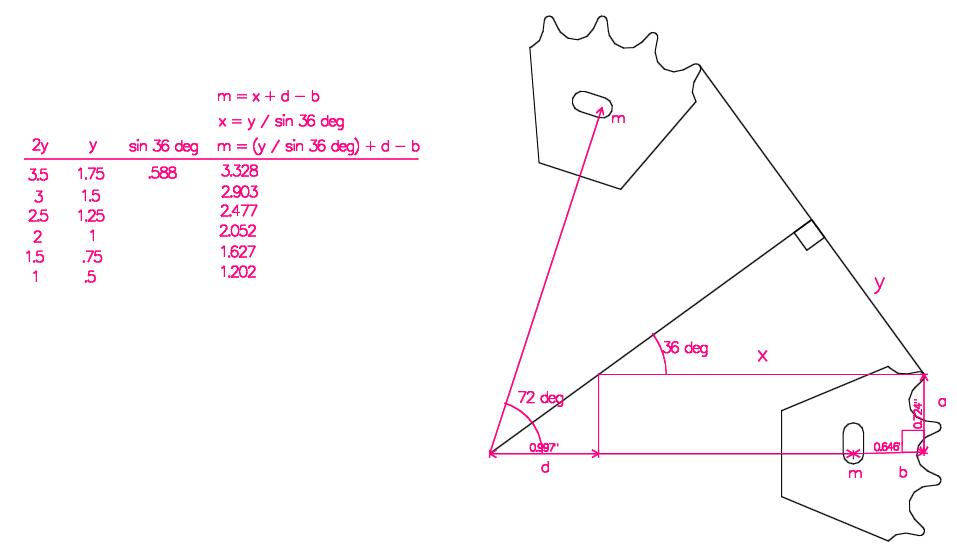
Click image to enlarge.
This exercise reminded me of what I both liked and hated about engineering: the problem solving through math, science and reason in general; the frustration in getting there.
One more problem solved…. doubtless more to come!