shimano patent appTwo of the Big Boys (the two biggest?) of bicycle component manufacturers, Shimano and SRAM, have both created quite a lot buzz with their patent applications for drivetrain components which would, in different ways, eliminate the front derailleur.

In January, the PTO published the patent application which Shimano filed for a frame integrated gearbox:


SRAM patent appAnd the application that SRAM filed for a crank mounted (not frame mounted!) derailleur was published by the PTO in May.

What I think this shows if that even the Big Boys realize there are inherent problems with the front derailleur on drive trains and that they have invested significantly in R & D and patent costs and fees to come up with creative, albeit super-complicated  ways around what has been a mainstay of bicycle transmissions.

The fact that these major players in the bike component marketplace are looking seriously at alternatives to the front derailleur has driven interest in VECTr.


20190925_212215
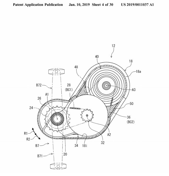
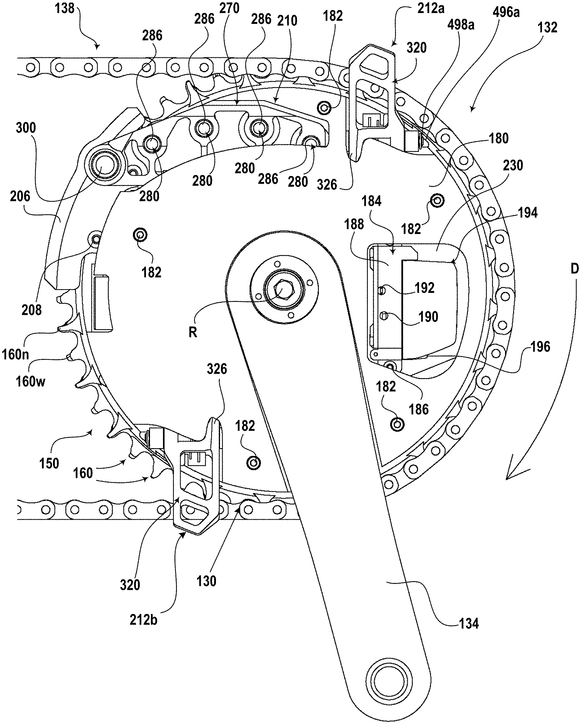
VECTr similarly eliminates the front derailleur and instead varies the size of the front driving gear by adjusting crank mounted gear segments. This keeps the chain in a consistent chainline. Shimano’s gearbox would do this, but only by requiring a heavy, complicated mechanism built into the bicycle’s frame. VECTr achieves gear changes while being mounted on existing bike cranks/bottom brackets, components compatible with standard frames. SRAM’s device would seemingly do this too, but it would also itself be a true derailleur and push the chain between only two discrete chainrings. Moreover, it would do so by incorporating tiny servo motors, batteries, a radio receiver, a timing computer and who knows what all else.

VECTr’s very great advantage over these proposed alternatives from SRAM and Shimano is that it achieves the same or better result than the devices described in the patent applications with a very much simpler design, and no doubt, at a very much reduced cost. Plus, VECTr is already patented!

I took VECTr for a quick spin around the neighborhood. Here is the uncut video of how it performed. I added some annotation just let you know when gear changes were taking place — they are virtually imperceptible otherwise.

There was a minor issue of a gear segment slipping into a lower position during a gear change. This was due to the controller being in a less-than-precise setting, being moved as it was by the lever/friction shifter attached to it. This could be remedied by using an index shifter (if one were calibrated to the rather large (relatively speaking) jumps between gear settings) or an electronic shifter, again properly calibrated.

Also, I think the springs biasing the locking pins in the gear segments are not as stiff and strong as they should be to catch the gear segment’s movement into the just the next gear setting and no further. I can solve this latter issue easily by using better springs, and will do so soon. The former issue would need to be addressed by someone more skilled in the fabrication of components than me, your humble inventor.

More Road Test Results

Posted: September 25, 2019 in Uncategorized

So, I conducted some more extensive road tests in April and May. The results were mixed. VECTr was definitely able to bear real life loads as I pedaled myself on neighborhood streets and up modest inclines. But I found that over more extended periods of riding, the chain would indeed slip, even when there was not much of a load on the chain. I did some more careful observations with the bike on the repair stand, and found that the teeth were not quite aligning with the links of the chain, and that this was the cause of the slippage. In January, I had redesigned the gear segments with tapped holes for receiving 1/4 inch bolts to secure them to the base plate. In the process, the teeth had changed a couple of millimeters from the prior design, and so were not syncing with the chain as the prior design had.

20190323_155640

Gear segments affixed with 1/4 inch bolts

Road tests also revealed a problem in using bolts to affix the gear segments to the base plate.  The force applied to the pedals to drive the chain passed through, as it were, the base plate to the gear segments, but as it did so, the threads of the bolts affixing the gear segments to the base plate dug into the grooves or guide tracks in which they would slide when being moved to a new radial position. Consequently, this force being concentrated on the bolts caused deformations in the edge of the guide tracks, and thus hindered the free movement of the gear segments when it came time for them to slide to their new radial position. This was a more serious problem that would need to be addressed

20190722_131710

Deformation of guide track

Although using bolts to both affix the gear segments to the base plate and to slide in the guide tracks was, in a sense, simpler and less expensive than other possible designs, the deformation of the surface of the guide tracks meant that I would need to find another way for the gear segments to slide without such problems. I spent a couple of weeks redesigning the gear segments with five instead of just four teeth, but in the proper dimensions to sync with the chain, and incorporating guiding flanges to distribute the load of the forces transferring from the base plate through the gear segments to the chain so as to prevent deforming the edge of the guide tracks.

20190924_101915

Gear Segment 8-5-19It took some time to get the new gear segments machined, but when mounted and tested for chain sync, they worked perfectly. I conducted some in-lab (utility room) and brief road tests, and they were able to drive the chain well. Gear changes, though, were inconsistent due to issues with the control assembly.


20190924_101608.jpg

In my last post I noted that the operation of VECTr tended to cause the controller assembly to go out of alignment and distort the bracket which mounted it on the bicycle frame. I therefore designed a new more sturdy and robust controller assembly and had it machined. Fitting the new assembly to the frame turned out to be more difficult than anticipated, but with some modifications, I was able to mount it and it was ready for another round of testing.

Initial in-lab tests show the new gear segments and controller assembly allow VECTr to run much more smoothly, confirming the potential within the ideas at the core of the Variably Expanding Chain Transmission design. See the video below for a demonstration of VECTr on the bicycle in the lab.

Next time: new road tests!

Road Tests!

Posted: April 7, 2019 in Uncategorized

So, since having the patent issue for VECTr, I made another model/prototype with which to conduct tests to see how it performs on an actual bicycle while bearing the (rather considerable) loads of an actual rider (me). The first step in order to do this was to switch out the bottom bracket on my Trek mountain bike with a 127.5 mm one so as to accommodate the somewhat larger size of VECTr. That took getting the appropriate tools and doing a little research on how to loosen the original one which seemed good and stuck. However, having successfully completed the bb switcheroo, installing VECTr was pretty straightforward.

20190323_160614

Once I fashioned a new, compact controller, I set about testing its operation on the bike while it was supported on a repair stand.

The test showed VECTr operating amazingly well!

The demonstration video (below) shows VECTr in action mounted on my bike. It is operated using a lever/friction shifter, so the shifts are not as precise as they would be with an index shifter, but, as you can see, they do not need to be for VECTr to change gears as quickly and efficiently as a derailleur/chainring system.

The next step was to take it on the road to see how it handled operating under load. This I was able to do this week. Again, VECTr performed remarkably well, and showed the current model very nearly to be a true prototype and in need of relatively little refinement to be production ready. I don’t have a video of road testing as it would require a frame-mounted camera to show anything interesting, so that will have to wait.

But, there were some specific findings that did emerge:

  • Bore loads well. VECTr was able to bear what I thought were moderate loads in the higher gear settings. I did not try to climb any significant hills, but VECTr performed well in the minor inclines and slow rolling starts of road riding. Obviously, I have no quantitative data – just my brief but real riding experience.
  • Compatible with rear cassette gears changes. VECTr was able to continue working even as the chainline varied with the changes in gear on the rear cassette.  I had not tested this on a model before and feared the varying chainline would prevent VECTr’s gear segments from engaging the chain without a chain guide. Such a fear turned out to be unfounded. Below is video of VECtr operating as the rear cassette changes gears with the bike on the repair stand.

  • No chain slippage. Critics often predicted that since VECTr has isolated points of contact with the chain, the higher tension on the chain at those points would cause the chain to slip, undermining the central task of a drive train. This did not happen.
  • No “lumpiness.” I did not feel any unevenness (or “lumpy” feel) in the pedaling. Some critics predicted that pentagonal path the chain formed while being driven by VECTr would result in such a lumpy feel, but I could not discern any. A more sensitive cyclist perhaps might, and precise power or torque measurements would probably reveal non-uniform results.

A couple of negatives:

  • I need to design and have machined a more sturdy and robust controller, as the operation of VECTr tended to drive the controller out of alignment and distort the frame-mounting bracket.
  • I need to utilize stiffer, yet smaller springs for the locking pins on each gear segment. Occasionally, a gear segment would not lock into place and slip inwardly under the force of engaging the chain. This was often rectified on the next pass through the controller and VECTr would continue to function properly. But a few times, the gear segment slid to where it could not engage the controller effectively, which pretty much prevented the pedal crank from turning. Using springs more appropriate to the space constraints of the gear segments should fix the issue. I expect this is an easy fix.

Over all, the positives of

  • a lighter,
  • more streamlined sprocket-mounted gearing system,
  • with more gear settings and
  • as reliable (or more so) than chainring/derailleur system

more than outweigh any negatives associated with the increased complexity of VECTr.

New Video of New Working Model

Posted: January 9, 2019 in Uncategorized

I’ve completed a new video announcing the issuance of a patent for VECTr, and showing the five-bolt design in action! Check it out below.

patent drawingThree years to the day after I filed the non-provisional patent application with the US Patent and Trademark Office, the examiner has allowed a patent for my Variably Expanding Chain Transmission to issue! Once the Notice of Allowance is mailed, and after I pay the requisite fee and submit any required changes or corrections to the application, the patent should issue in a few weeks! At that time, VECTr will no longer be “patent pending,” but an actual patented invention!

UPDATE:  On January 1, 2019, patent number 10,167,055 was issued for Variably Expanding Chain Transmission!

So, testing and adjustments were progressing in August 2017, until . . .

Hurricane Harvey struck Houston, and well, things got off-track. We were fine, but a lot of people were not, and the day job prevented invention work for a while.

But, the latter has resumed, and progress has been made. Here’s a shot of the working model working.

20180301_111641

VECTr – Variably Expanding Chain Transmission (Patent pending)

A video of the 5 bolt design in action will be coming soon! Check back for updates.


More Improvements

Posted: July 31, 2017 in Uncategorized

20170102_174008

Chain ring bolts interfere with movement of gear segments

It has been a while since I updated the progress being made on VECTr (in part because that progress has been slowed by my day job consuming the free time I would have devoted to inventing). Well, a couple of developments have taken place since January. First, while the 110 BCD five gear segment design showed promise, the placement of the bolts in that design interfered with the movement of the gear segments.

So in January, I modified the design of the base plate to allow the free movement of the gear segments, and began testing the design in February.


20170730_213150

Throughout February and March, I tested various designs for the locking pin, trying to find one that would keep the pin perpendicular to the plane of the base plate while sliding into and out of the locking notches in the base plate. In addition, I was trying to figure out the best spring type to bias the pin into the locked position, a type that would fit into the very small space between the gear segment and the base plate.  The locking pin/spring combination is really the key to VECTr being able to achieve expanding gears at a light weight and hopefully low production cost.


One other improvement was to affix the control plate guide more securely to the frame. In the end, I replaced the temporary wooden bracket with a steel one I fashioned which is much more durable, and will probably be incorporated into the final product design.

20170730_212926

New 5-Bolt base plate with gear segments and control plate guide affixed with steel bracket.

Now, as I had indicated in the prior blog post, I still need to find the proper angles for the control plates that will unlock and move the gear segments both from inner to outer positions, and vice versa.  We are getting close!


In the last post, I said that I had been focusing my attention on a 5-arm 110 BCD version of VECTr that used the same idea for the locking pin as the version in the video.  That basic idea consists of the locking pin moving laterally when contacting the control plates to unlock the gear segment, and being pushed along the contour of the control plate into its new radial position as the crank turns.  I had said that I had been trying to get this to work, and the fact that I was trying, meant that I was unsuccessful.

20170102_174349

Old version of control plate mechanism, with long sweeping outside plate (on the left).

Well, it’s a funny thing about tinkering that sometimes ideas strike you while trying to do something else. When I was working on the laterally locking pin design last spring, I was indeed unsuccessful, and so went back to the drawing board (or CAD program) and came up with perpendicularly drawn locking pin design.  And in the fall, I was trying to get this new design to work, when, seeing some parts from the old design on my desk, I wondered again why it wouldn’t work.  So I reassembled them, but tested them with the control plates for the new design, and what to my wondering eyes should happen, but the hybrid of old and new worked (sort of).  I discovered that it wasn’t the lateral locking pin that was the problem, but the control plates (which seemed necessary for the version in the video and had worked there — see image to the right).


Instead of the long sweep for the outside control plate, the new design had two simple angled control plates, but they seemed able to unlock and re-position the gear segment of the old design, but not as smoothly as they should.  So, as a result, for the last few weeks, I have revived the old design and tested various shapes for the control plates.

20170127_113644
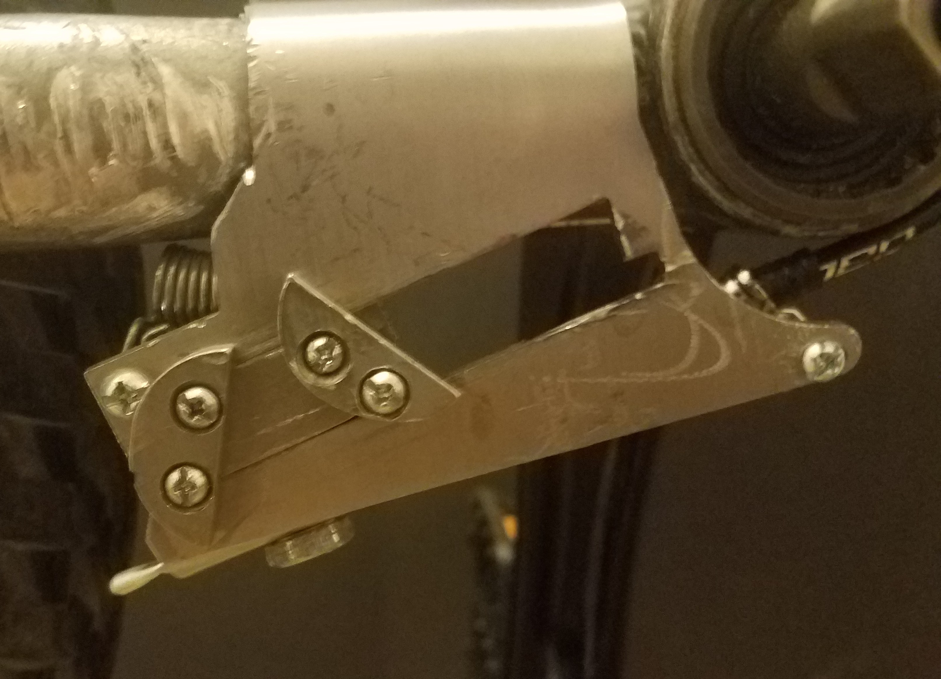
Finally, I found that by modifying the inside control plate from the old design, it would contact the locking pin on the gear segment at an appropriate angle to unlock it and slide it to the desired radial position.  (It took much trial and error to find the appropriate angle — a better understanding of geometry and the physics of friction might have led to a good design, a priori, but what can you do . . . .)

20170127_113723

Gear segment being moved to the outside of the expansion arm by contacting the new inside control plate.


20170127_113728

The gear segment in the new outermost position with its locking pin released to lock the gear segment in place.


So, this is (hopefully) the last major hurdle to finalizing a truly functional design.  I know of many smaller hurdles and tweaks that will be necessary, and I will probably discover others, but I feel good that VECTr is getting closer to the marketable stage.

Further Refinements

Posted: January 6, 2017 in Uncategorized

While the original video of VECTr garnered positive feedback and interest, there were many questions about its operation as well as suggestions for improvement.  (You can see a representative sample in the comments on various pages of the this website.)  Easily, the number one criticism was that the expanding chainring design has been tried and found commercially wanting.  As I continue to point out, there have been many expanding chainring designs that have not had sustainable commercial success, but the differences among them probably account for their varying degrees of profitability.  Trying to find the simplest, most reliable design producible for the least cost is the true challenge in design in general, and specifically in the expanding chainring transmission game.

20170102_173953
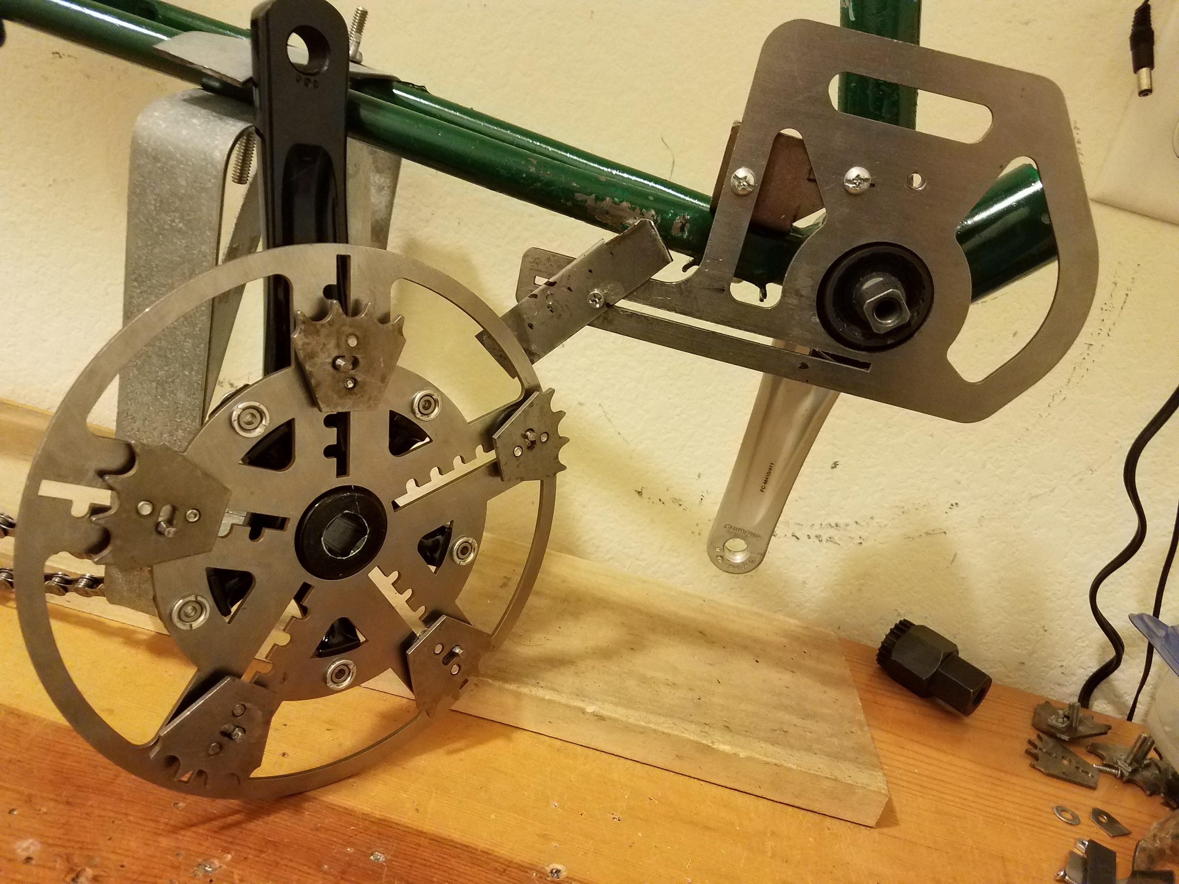
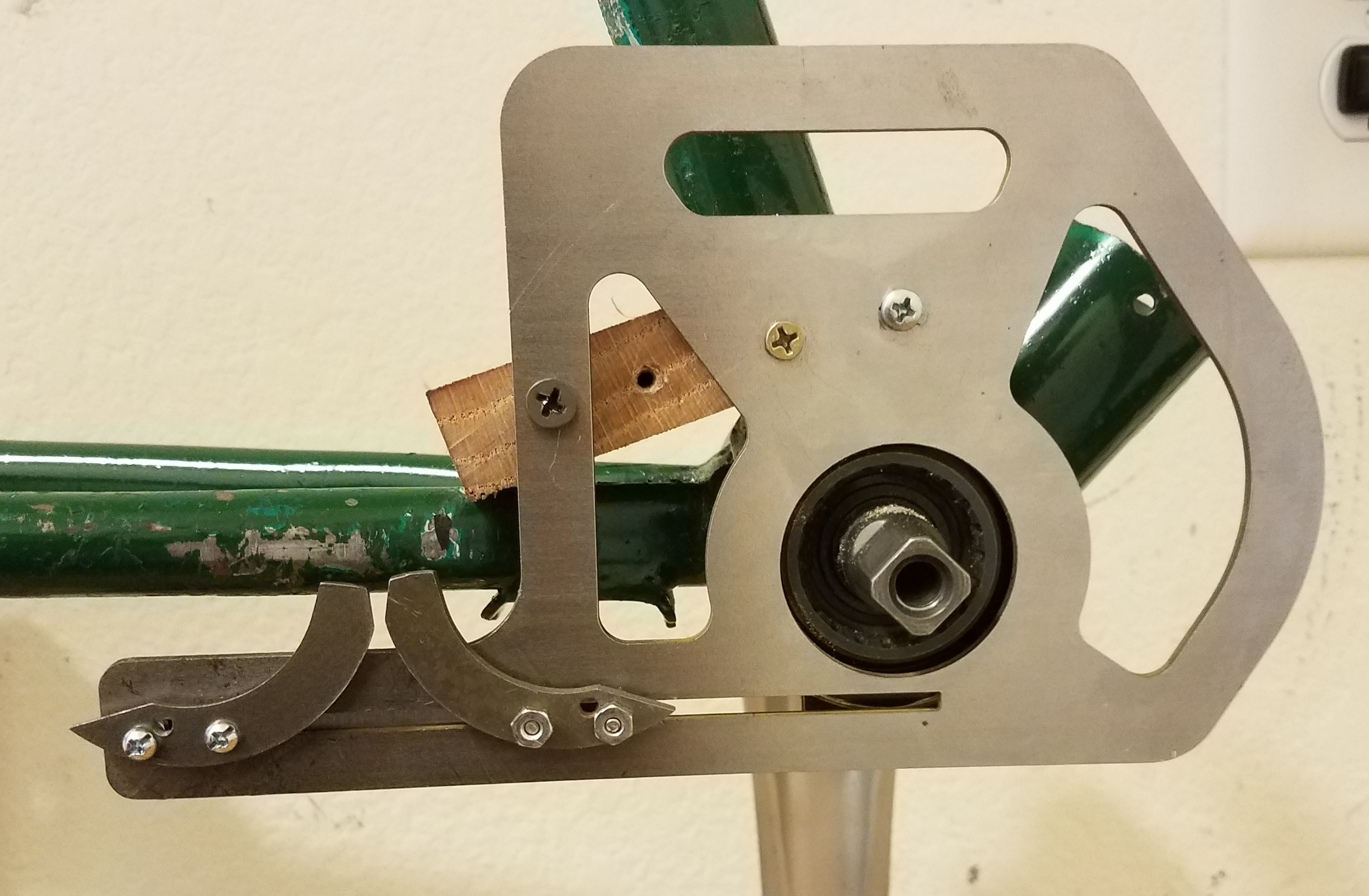
There were concerns specific to the VECTr design which I have spent my time trying to address.  The first had to do with the smoothness of the operation.  It has always been an aim of the design process to make a device which is compatible with current bicycle standards, and so I made a four gear segment mechanism which could be fitted to the 64 BCD fittings of a MTB crank arm.

It was noted, however, that this made the operation of VECTr appear “lumpy” and uneven, and viewers thought it would make for an uncomfortable ride. Yet, increasing the number of gear segments would increase steps between the gear ratios, and thus limit the range of settings for the device.

20170102_174309a
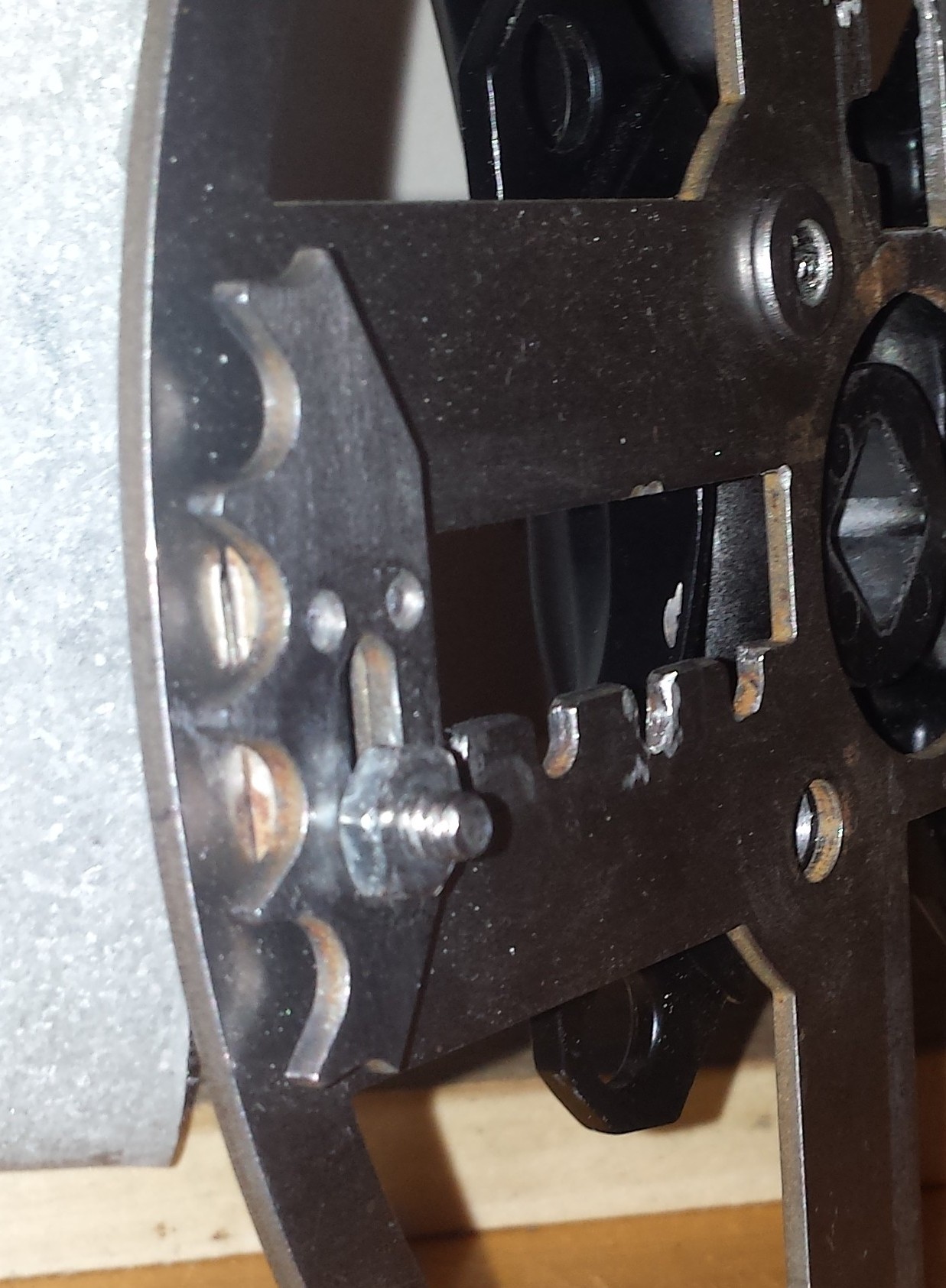
Also, the design of the locking/adjustment mechanism of the gear segment consisted of three pieces for the sliding motion, plus a pin/bolt and spring for the locking motion, in addition to the actual chain-engaging gear segment.  These were all held together with simple blind rivets, which I knew were none too strong, and probably would not hold up to the stresses of actual road use.  In working up some cost estimates for the manufacture of VECTr in that iteration of the design, it became clear that it would be difficult to entice a manufacturer to license the design, or for me to make them out of my garage.  I thought, too, that simplifying the design of the gear segment mechanism would decrease the weight and offset the additional mass of added gear segments.

20170102_174008
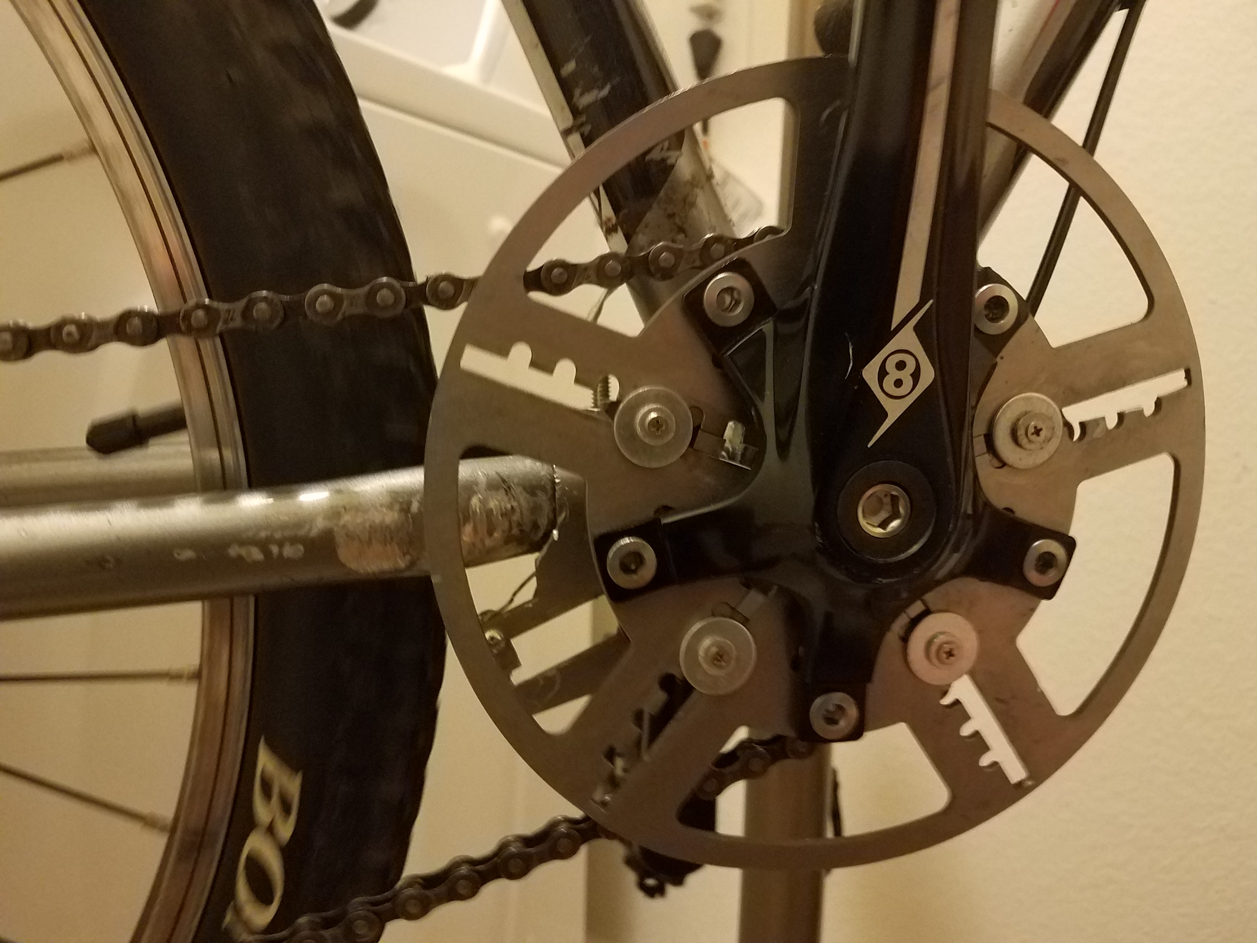
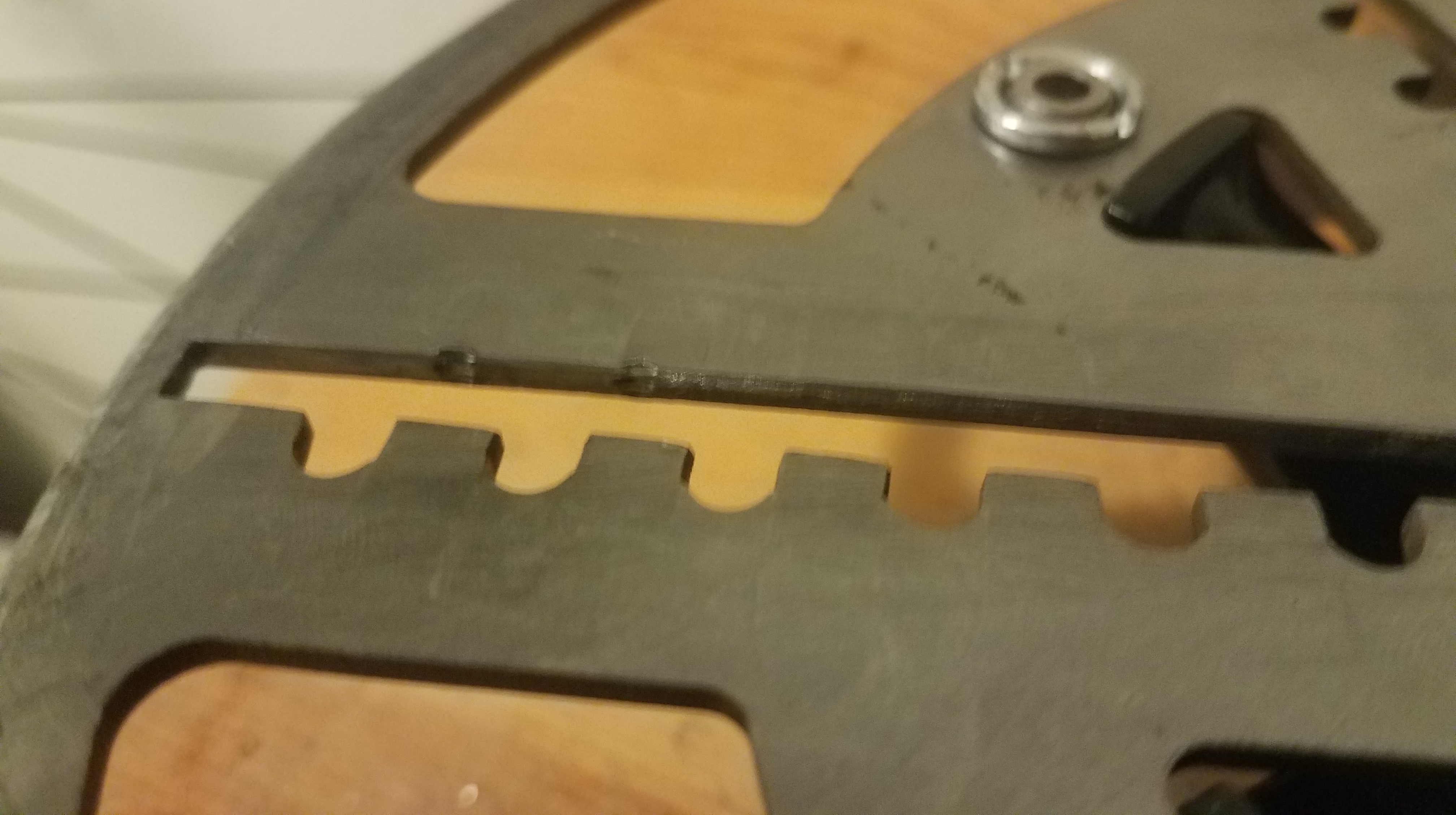
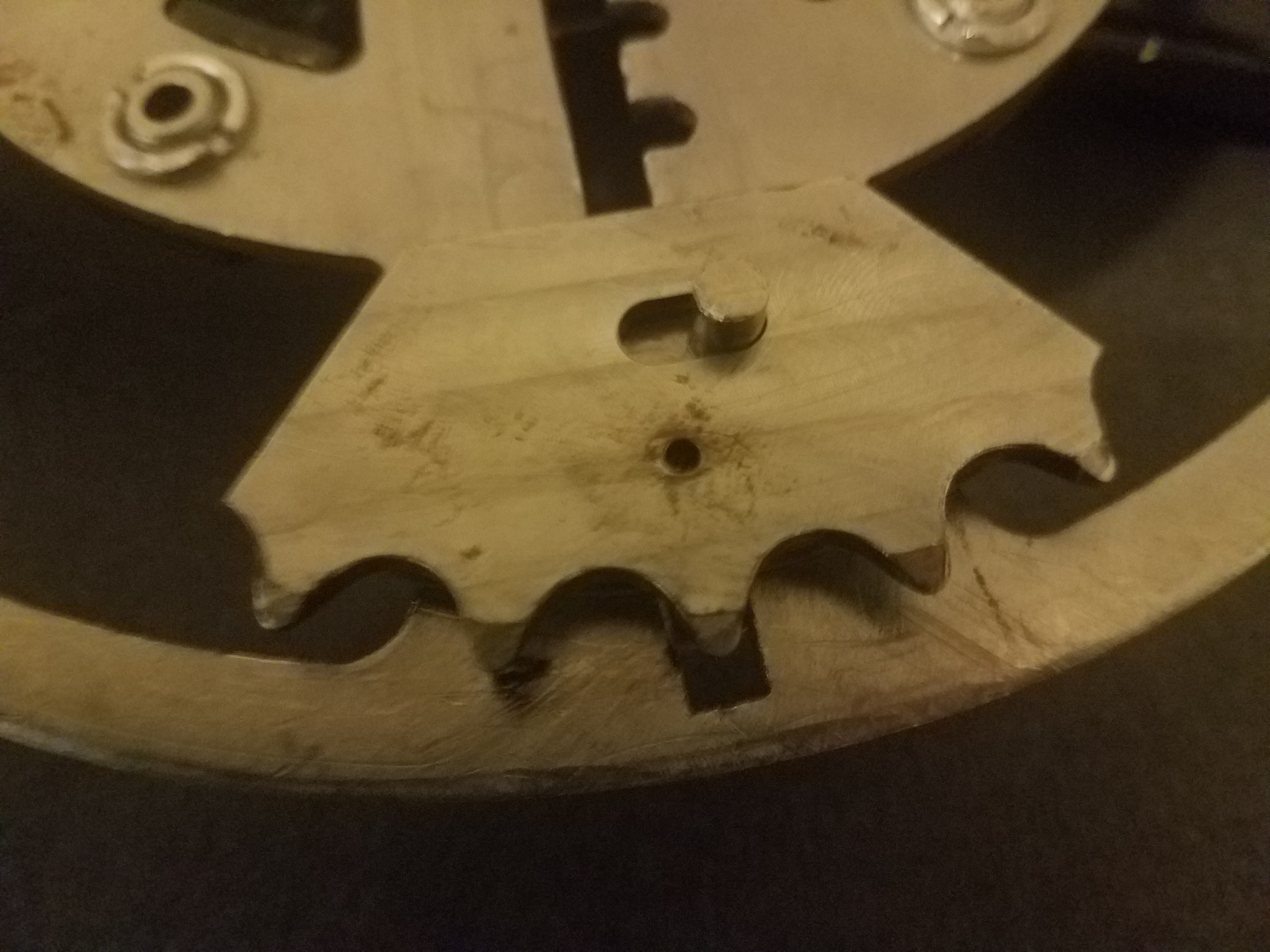
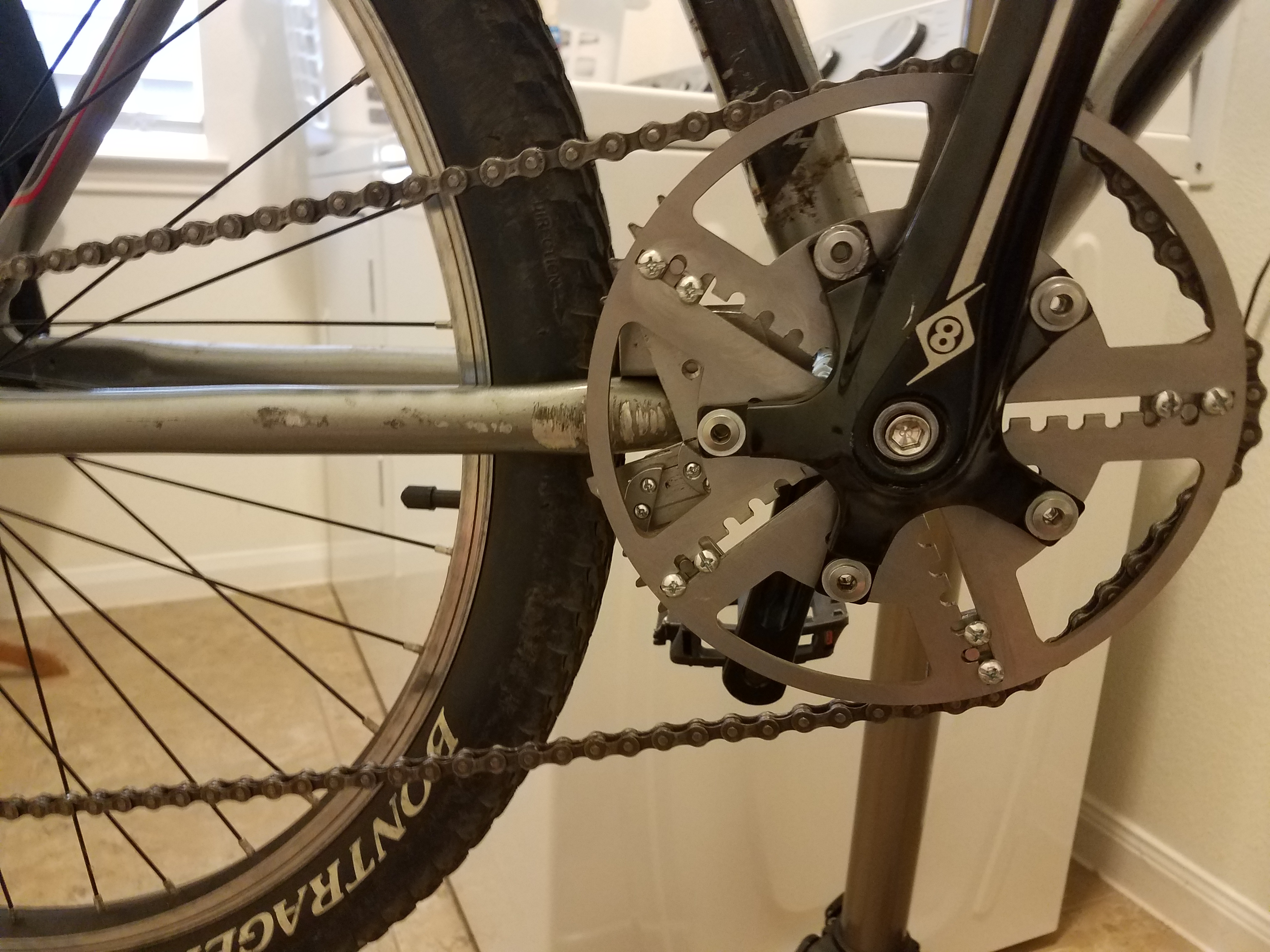
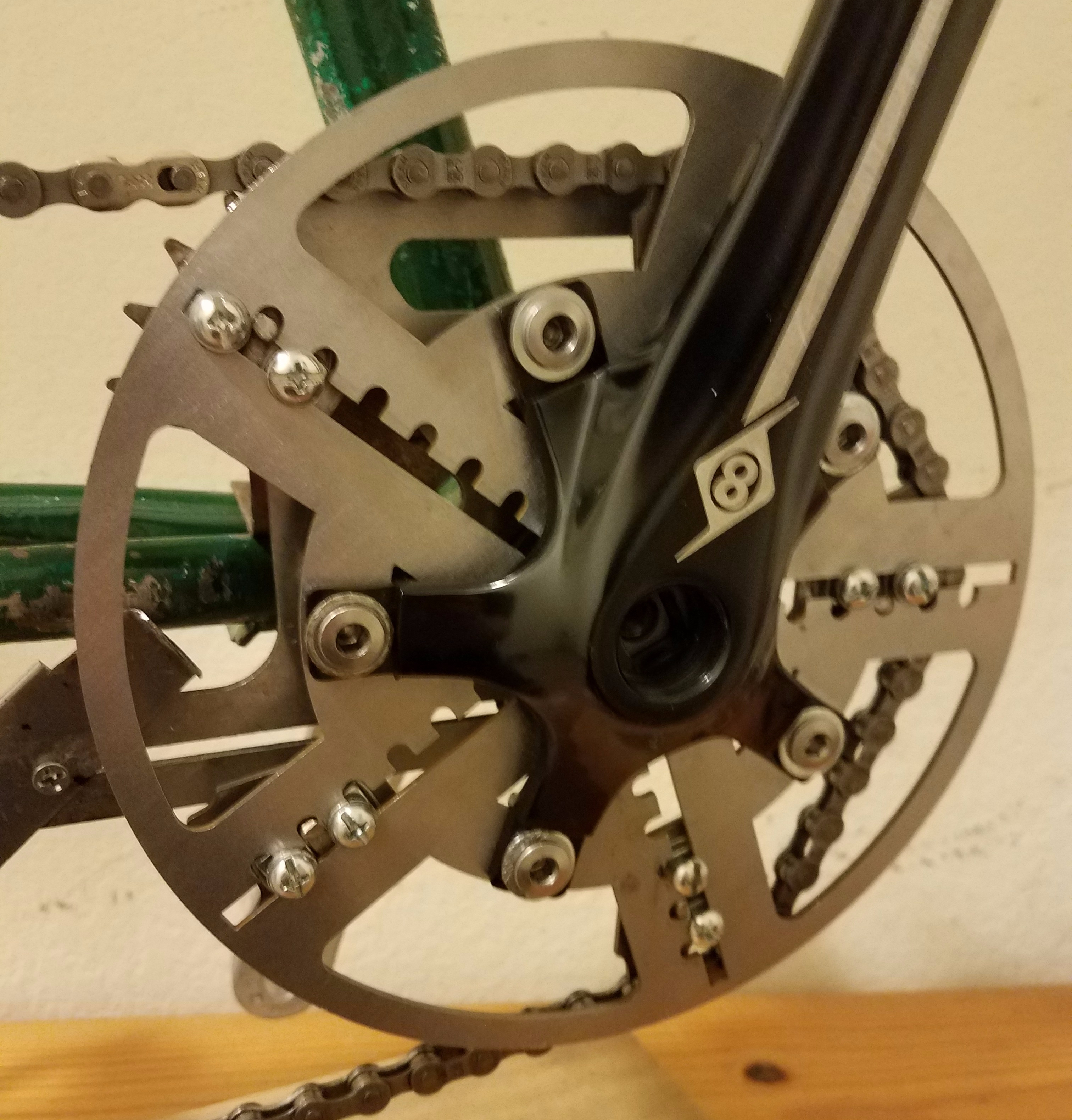
The result of rethinking these issues led me to design VECTr with five expansion arms (fitted for 110 BCD cranks) and five gear segments which would slide within narrower channels, still having notches on one edge into which a locking pin would fit.  In a prior blog post I detailed how I had to call upon my trigonometric acumen (latent and seldom used as it was) to work out the proper spacing of the notches for the five arm design.

20170102_174223
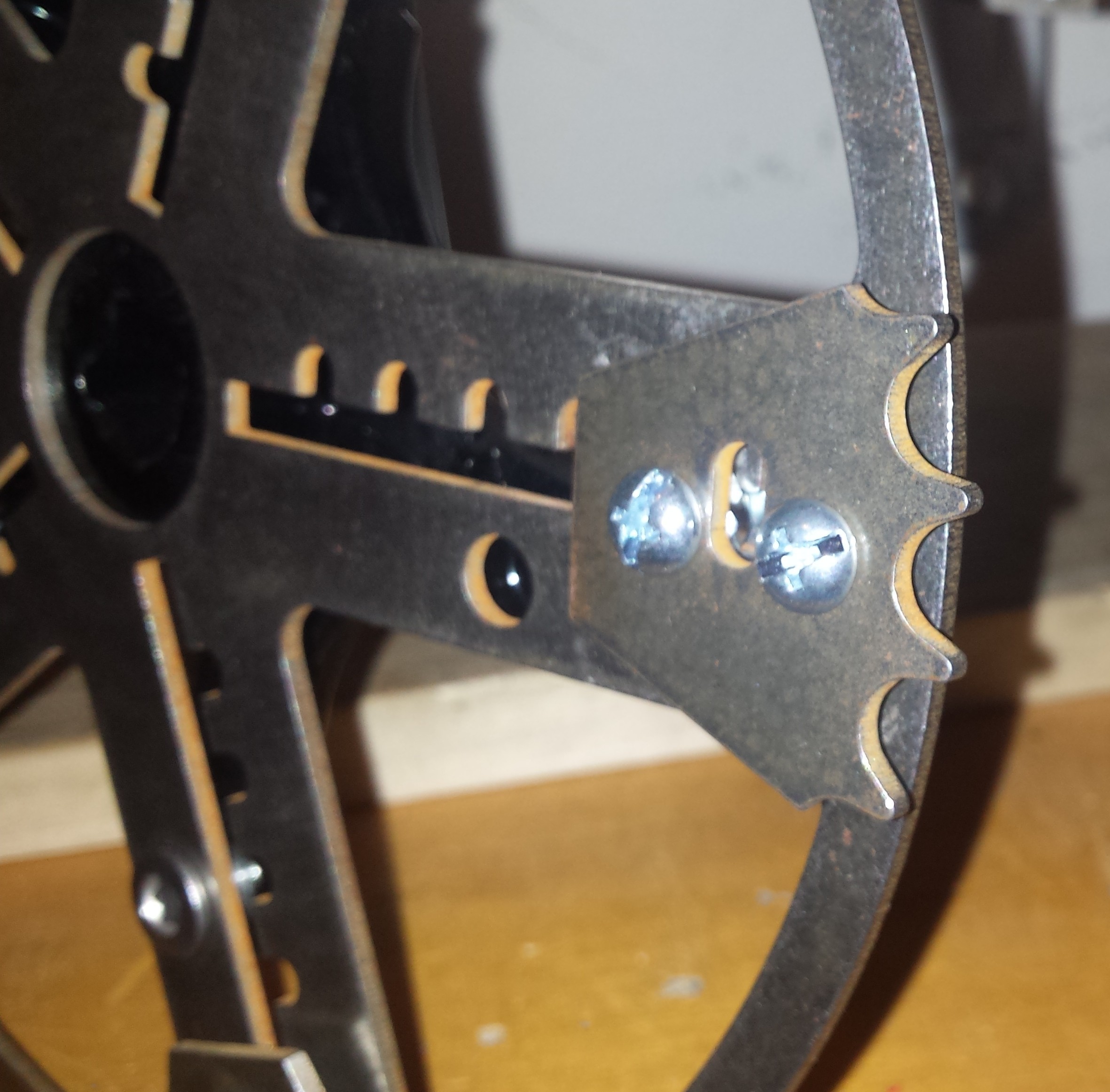
In this new design, I replaced the three-piece sliding parts with simple bolts (which also took the place of the rivets) and the locking bolt sliding with the rest; it would be biased into locking position by an external elastic band or other small spring.

I spent much of my time working on VECTr this past year (when I could work on it) trying to get this design to work, as well as working to make the control mechanism compatible with a Shimano indexed shifter.  I detail some of that work in a prior blog post, too.

Given that I say that I tried to get this new design to work is a pretty good indication that it was not successful.  I will have to let you know the insights this process gave me that led me to the current design, which I think shows even greater promise.